

.jpg?x-oss-process=image/resize,w_100/quality,q_100)
.jpg?x-oss-process=image/resize,w_100/quality,q_100)
.jpg?x-oss-process=image/resize,w_100/quality,q_100)
.jpg?x-oss-process=image/resize,w_100/quality,q_100)
.jpg?x-oss-process=image/resize,w_100/quality,q_100)
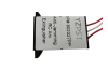
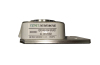
YZPST-BT151-650R-L
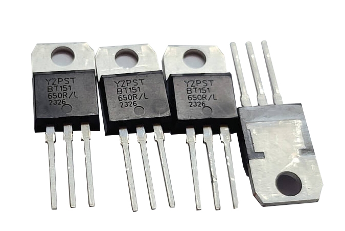
BT151 Series 12A SCRs
YZPST-BT151-650R-L
DESCRIPTION:
Glasspassivated thyristors in aplastic envelope, The BT151 SCRs series is suitable to fit all modes of control,found in applications such as overvoltage crowbar protection, motor control circuits in power tools and kitchen aids, inrush current limiting circuits, capacitive discharge ignition and voltage regulation circuits
.jpg)


BT151 Series 12A SCRs
YZPST-BT151-650R-L
650V BT151-650R-L TO-220 12A SCR
DESCRIPTION:
Glasspassivated thyristors in aplastic envelope, The BT151 SCRs series is suitable to fit all modes of control,found in applications such as overvoltage crowbar protection, motor control circuits in power tools and kitchen aids, inrush current limiting circuits, capacitive discharge ignition and voltage regulation circuits
MAIN FEATURES
|
Symbol |
Value |
Unit |
|
IT(RMS) |
12 |
A |
|
VDRM VRRM |
650 |
V |
|
IGT |
15 |
mA |
ABSOLUTE MAXIMUM RATINGS
|
Parameter |
Symbol |
Value |
Unit |
|
Storage junction temperature range |
Tstg |
-40 ~ 150 |
℃ |
|
Operating junction temperature range |
Tj |
-40~ 125 |
℃ |
|
Repetitive peak off-state voltage (T =25℃) |
VDRM |
650 |
V |
|
Repetitive peak reverse voltage (T =25℃) |
VRRM |
650 |
V |
|
RMS on-state current (T = 105℃) |
IT(RMS) |
12 |
A |
|
Non repetitive surge peak on-state current ( 180° conduction angle, F=50Hz) |
ITSM |
100 |
A |
|
Average on-state current ( 180° conduction angle) |
IT(AV) |
8 |
A |
|
I2t value for fusing (tp= 10ms) |
I2t |
45 |
A2S |
|
Critical rate of rise of on-state current (I =2 ×IGT, tr ≤ 100 ns) |
di/dt |
50 |
A/μS |
|
Peak gate current |
IGM |
4 |
A |
|
Average gate power dissipation |
PG(AV) |
1 |
W |
ELECTRICAL CHARACTERISTICS (T=25℃unless otherwise specified)
|
Symbol |
Test Condition |
|
Value |
Unit |
|
IGT |
V = 12V R = 140Ω |
MAX. |
15 |
mA |
|
VGT |
MAX. |
1.3 |
V |
|
|
VGD |
VD=VDRM Tj=125℃ R= 1KΩ |
MIN. |
0.2 |
V |
|
IL |
IG= 1.2IGT |
MAX. |
50 |
mA |
|
IH |
IT=50mA |
MAX. |
30 |
mA |
|
dV/dt |
VD=2/3VDRM Gate Open Tj=125℃ |
MIN. |
400 |
V/μs |
STATIC CHARACTERISTICS
| Symbol | Parameter | Value(MAX.) | Unit | |
| VTM | ITM =23A tp=380μs | Tj =25℃ | 1.6 | V |
| IDRM | VD=VDRM VR=VRRM | Tj =25℃ | 5 | μA |
| IRRM | Tj =125℃ | 2 | mA | |
Thermal Resistances
| Symbol | Parameter | Value | Unit | |
| TO-220M1 | 60 | |||
| Rth(j-a) | junction to ambient | TO-220FW | 50 | |
| TO-252 | 70 | |||
| TO-220M1 | 1.5 | ℃/W | ||
| Rth(j-c) | Junction to case | TO-220FW | 4.5 | |
| TO-252 | 2 | |||
TO-220 Package Mechanical Data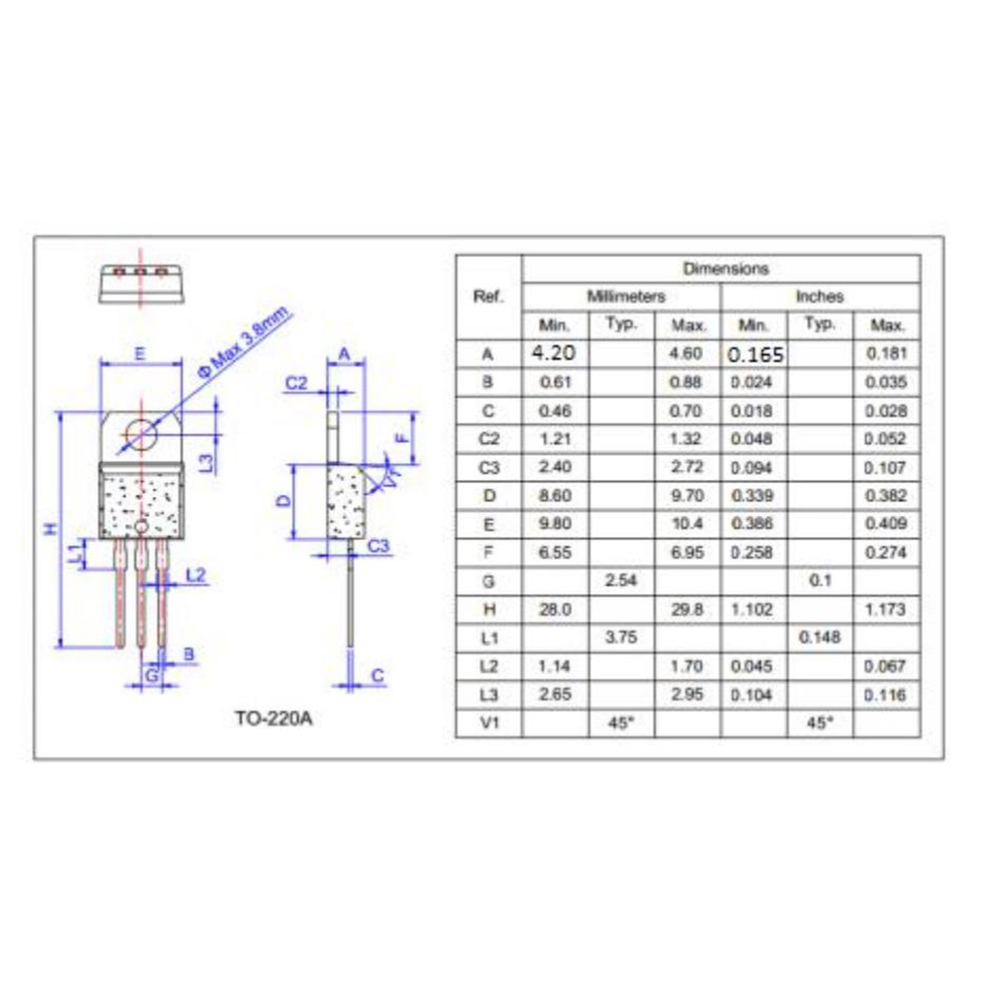
Related Products