


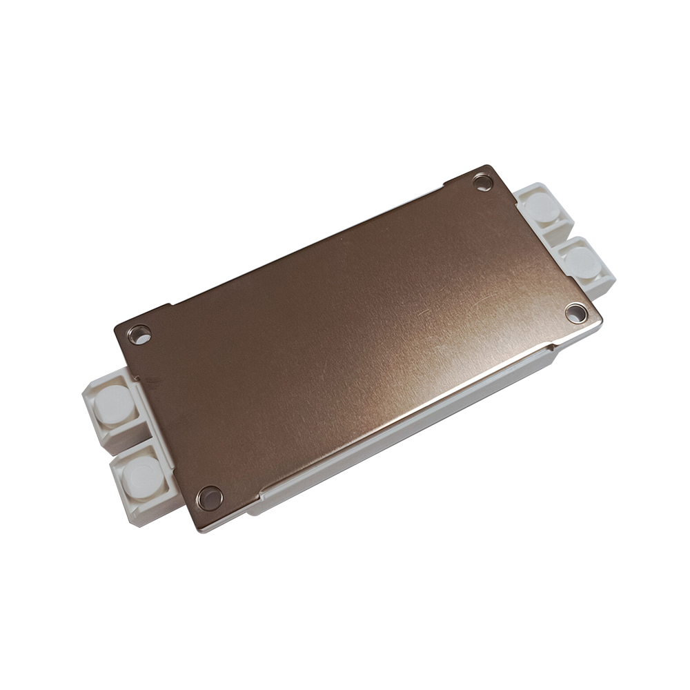
YZPST-G900WB120B6TC
1200V 900A IGBT Module
P/N: YZPST-G900WB120B6TC
PRODUCT FEATURES
IGBT CHIP(Trench+FS)
Low saturation voltage and positive temperature coefficient
Fast switching and short tail current
Free wheeling diodes with fast and soft reverse recovery
Temperature sense included
APPLICATIONS
AC motor control
Motion/servo control
Inverter and power supplies
Photovoltaic/Fuel cell
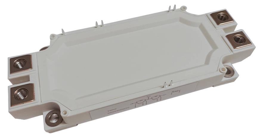
IGBT-ABSOLUTE MAXIMUM RATINGS(TC =25°C unless otherwise specified)
| Symbol | Parameter/Test Conditions | Values | Unit | |
| VCES | Collector Emitter Voltage | TJ=25℃ | 1200 | V |
| VGES | Gate Emitter Voltage | ±20 | ||
| IC | DC Collector Current | TC=25℃, TJmax =175℃ | 880 | |
| TC=95℃, TJmax =175℃ | 900 | A | ||
| ICM | Repetitive Peak Collector Current | tp=1ms | 1200 | |
| Ptot | Power Dissipation Per IGBT | TC=25℃, TJmax =175℃ | 3125 | W |
Diode-ABSOLUTE MAXIMUM RATINGS ( TC =25°C unless otherwise specified)
| Symbol | Parameter/Test Conditions | Values | Unit | |
| VRRM | Repetitive Reverse Voltage | TJ=25℃ | 1200 | V |
| IF(AV) | Average Forward Current | 900 | A | |
| IFRM | Repetitive Peak Forward Current | tp=1ms | 1200 | |
| I2t | TJ =150℃, t=10ms, VR=0V | 45 | kA2s | |
IGBT-inverter
ELECTRICAL CHARACTERISTICS (TC =25°C unless otherwise specified)
| Symbol | Parameter/Test Conditions | Min. | Typ. | Max. | Unit | ||
| VGE(th) | Gate Emitter Threshold Voltage | VCE=VGE , IC=24mA | 5 | 5.8 | 6.5 | ||
| Collector Emitter | IC=900A, VGE=15V, TJ=25℃ | 1.9 | 2.3 | ||||
| VCE(sat) | Saturation Voltage | IC=900A, VGE=15V, TJ=125℃ | 2.2 | V | |||
| IC=900A, VGE=15V, TJ=150℃ | 2.25 | ||||||
| ICES | Collector Leakage Current | VCE=1200V, VGE=0V, TJ=25℃ | 1 | mA | |||
| VCE=1200V, VGE=0V, TJ=150℃ | 10 | ||||||
| IGES | Gate Leakage Current | VCE=0V,VGE=±20V, TJ=25℃ | -400 | 400 | nA | ||
| RGint | Integrated Gate Resistor | 0.7 | Ω | ||||
| Qg | Gate Charge | VCE=900V, IC=900A , VGE=15V | 3.1 | µC | |||
| Cies | Input Capacitance | VCE=25V, VGE=0V, f =1MHz | 43.2 | nF | |||
| Cres | Reverse Transfer Capacitance | 2.07 | nF | ||||
| td(on) | Turn on Delay Time | VCC=600V,IC=900A RG =1.5Ω , | TJ=25℃ | 100 | ns | ||
| VGE=±15V, | TJ=150℃ | 110 | ns | ||||
| tr | Rise Time | Inductive Load | TJ=25℃ | 85 | ns | ||
| TJ=150℃ | 95 | ns | |||||
| td(off) | Turn off Delay Time | VCC=600V,IC=900A RG =1.5Ω , | TJ=25℃ | 530 | ns | ||
| VGE=±15V, | TJ=150℃ | 580 | ns | ||||
| tf | Fall Time | Inductive Load | TJ=25℃ | 65 | ns | ||
| TJ=150℃ | 215 | ns | |||||
| TJ=25℃ | 55 | mJ | |||||
| Eon | Turn on Energy | TJ=125℃ | 85 | mJ | |||
| VCC=600V,IC=900A RG =1.5Ω , | TJ=150℃ | 95 | mJ | ||||
| VGE=±15V, | TJ=25℃ | 45 | mJ | ||||
| Eoff | Turn off Energy | Inductive Load | TJ=125℃ | 58 | mJ | ||
| TJ=150℃ | 63 | mJ | |||||
| ISC | Short Circuit Current | tpsc≤10µs , VGE=15V | 2200 | A | |||
| TJ=150℃,VCC=800V | |||||||
| RthJC | Junction to Case Thermal Resistance (Per IGBT) | 0.048 | K /W | ||||
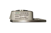
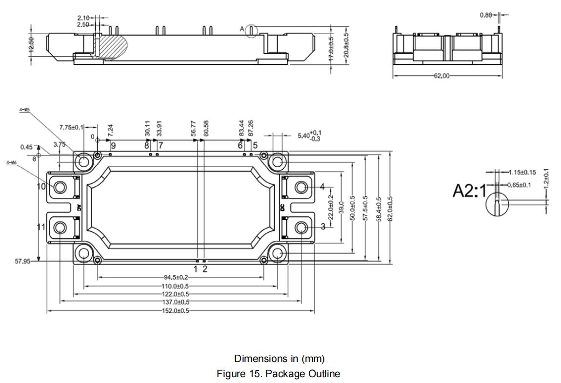
Package Outline
Related Products