
.jpg?x-oss-process=image/resize,w_100/quality,q_100)
.jpg?x-oss-process=image/resize,w_100/quality,q_100)
.jpg?x-oss-process=image/resize,w_100/quality,q_100)
.jpg?x-oss-process=image/resize,w_100/quality,q_100)

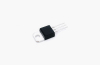
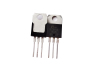
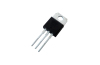
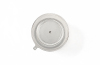
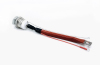
YZPST-BTA216X-600B
BTA216X-600B TRIACS
DESRCRIPTION:
Due to separation glass passivation, these devices have good
performance at dv/dt and reliability. The Triac series is suitable for
general purpose AC switching. They can be used as an On-Off
function in the applications such as static relays, heating regulation,
or for phase control operation in light dimmers, motor speed controllers.

description1
Zipper closure
1/5 zip athletic pullovers for men. Stretchy, lightweight, fast-drying
fabric for superior performance.
REGULAR FIT - US standard sizes. An athletic fit that sits close to the
body
for a wide range of motion, designed for optimal performance and all day
comfort.
FEATURES - Quarter zip closure;Thumbholes on long sleeves to keep them
in
place during workout
DESCRIPTION

BTA216X-600B TRIACS
DESRCRIPTION:
Due to separation glass passivation, these devices have good
performance at dv/dt and reliability. The Triac series is suitable for
general purpose AC switching. They can be used as an On-Off
function in the applications such as static relays, heating regulation,
or for phase control operation in light dimmers, motor speed
controllers.

MAIN FEATURES
|
Symbol |
Value |
Unit |
|
IT(RMS) |
16 |
A |
|
VDRM/VRRM |
600 |
V |
|
IGT |
≤10 |
mA |
ABSOLUTE MAX I MUM RATINGS
| Symbol | PARAMETER | Value | Unit | |
| IT(RMS) | RMS on-state current(full sine wave) | TO-220.Non-Ins TC≤99℃ | 16 | A |
| Non repetitive surge peak on-state current | t=20ms | 140 | ||
| ITSM | (full sine wave, Tj=25℃) | t= 16.7ms | 150 | A |
| I2t | I2t Value for fusing | t= 10ms | 98 | A2S |
| di/dt | Repetitive rate of rise of on-state Current after triggering | ITM = 20 A; IG = 0.2 A dIG/dt = 0.2 A/us | 100 | A/μs |
| IGM | Peak gate current, | — | 2 | A |
| VGM | Peak gate voltage | — | 5 | W |
| PGM | Peak gate power | — | 5 | W |
| PG(AV) | Average gate power | over any 20 ms period | 0.5 | W |
| Tstg | Storage junction temperature range | -40 to +150 | ℃ | |
| Tj | Operating junction temperature range | 125 | ℃ | |
ELECTRICAL CHARACTERISTICS (Tj = 25。C, unless otherwise specified)
STATIC CHARACTERISTICS
| Symbol | Parameter | Test Condition | Quadrant | Value | Unit | ||
| MIN | TYPE | MAX | |||||
| IGT | Gate trigger current | VD= 12V, IT=0. 1A | Ⅰ-Ⅱ-Ⅲ | - | - | 10 | mA |
| VD= 12V, IT=0. 1A | - | 0.7 | 1.5 | ||||
| VGT | Gate trigger voltage | VD=400V, IT=0. 1A,Tj= 125°C | 0.25 | 0.4 | - | V | |
| VT | On-state voltage | IT=20A | - | 1.2 | 1.5 | V | |
| IH | Holding current | VD= 12V, IGT=0. 1A | Ⅰ-Ⅱ-Ⅲ | - | - | mA | |
| Ⅰ-Ⅲ | - | - | 60 | mA | |||
| IL | Latching current | VD= 12V, IGT=0. 1A | Ⅱ | - | - | 90 | mA |
| ID | Off-state leakage current | VD = VDRM(max); Tj= 125 ˚C | - | 0.1 | 0.5 | mA | |
DYNAMIC CHARACTERISTICS
| Symbol | Parameter | Test Condition | Value | Unit | |
| MIN | TYPE | ||||
| dVD/dt | Critical rate of rise of off- state voltage | VDM = 67% VDRM(max); Tj = 125 ˚C | 1000 | 4000 | V/us |
| exponential waveform; gate open circuit | |||||
| dIcom/dt | Critical rate of change of commutating current | VDM = 400 V; Tj = 125 ˚C; IT(RMS) = 16A; without snubber; gate open circuit | 28 | A/ms | |
| T | Gate controlled turn-on time | ITM = 20 A; VD = VDRM(max) ; IG = 0. 1 A; dIG/dt = 5 A/µs | 2 | us | |
| tgt | |||||
PACKAGE MECHANICAL DATA

Related Products