
.jpg?x-oss-process=image/resize,w_100/quality,q_100)
.jpg?x-oss-process=image/resize,w_100/quality,q_100)
.jpg?x-oss-process=image/resize,w_100/quality,q_100)
.jpg?x-oss-process=image/resize,w_100/quality,q_100)

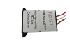
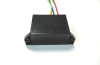
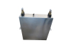
YZPST-MFC200-16
Features:
- Heat transfer through aluminium-nitride ceramic isolated metal baseplate
- Hard soldered joints for high reliability
- Thyristor with amplifying gate
Typical applications:
- DC motor control - AC motor soft starters
- Temperature control
- Professional light dimming


YZPST-MFC200-16
THYRISTOR / DIODE MODULE
Features:
- Heat transfer through aluminium-nitride ceramic isolated metal baseplate
- Hard soldered joints for high reliability
- Thyristor with amplifying gate
Typical applications:
- DC motor control - AC motor soft starters
- Temperature control
- Professional light dimming
Reverse blocking - Off-state
| Device Type | VRRM (1) | VDRM (1) | VRSM (1) |
| YZPST MFC200 | 1600 V | 1600 V | 1700 V |
VRRM = Repetitive peak reverse voltage
VDRM = Repetitive peak off-state voltage
VRSM = Non repetitive peak reverse voltage (2)
| Repetitive reverse and off-state peak leakage current | IRRM, IDRM | 70 mA (3) |
| Critical rate of rise of off-state voltage | dv/dt | 1000 V/µs (4) |
Conducting
| Parameter | Symbol | Min | Max | Typ | Unit | Conditions | |
| Average on-state / forward current | ITAV, IFAV | 216 | A | 50 Hz sine wave,180o conduction, | |||
| Tc = 85 °C | |||||||
| RMS on-state / forward current | ITRMS, IFRMS | 340 | A | 50 Hz sine wave,180° conduction, | |||
| Tc = 85 °C | |||||||
| Surge non repetitive current | ITSM, IFSM | 6.8 | kA | 50 Hz sine wave | |||
| Half cycle | |||||||
| I squared t | I2 t | 231 | kA2s | VR = 0 | |||
| Tj = Tjmax | |||||||
| Peak on-state / forward voltage | VTM, VFM | 1.1 | V | On-state current 200 A, Tj = Tjmax | |||
| Threshold voltage | VT(TO) | 0.8 | V | Tj = Tjmax | |||
| On-state slope resistance | rT | 1.4 | mΩ | Tj = Tjmax | |||
| Holding current | IH | 150 | mA | Tj = 25 °C | |||
| Latching current | IL | 200 | mA | Tj = 25 °C | |||
| Critical rate of rise of on-state current | di/dt | 500 | A/µs | IG = 5 IGT, tr= 1 µs, Tj = Tjmax, non rep. | |||
| RMS isolation voltage | VINS | 3000 | V | AC 50 Hz, 60 s | |||
Triggering
| Parameter | Symbol | Min | Max | Typ | Unit | Conditions | |
| Gate current | IGT | 150 | mA | VD = 6 V; RL = 6 Ω; Tj = 25 °C | |||
| Gate voltage | VGT | 2 | V | VD = 6 V; RL = 6 Ω; Tj = 25 °C | |||
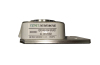
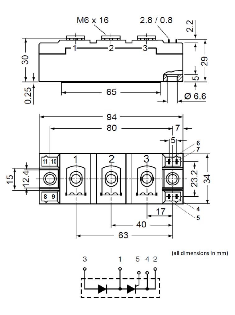
OUTLINE AND DIMENSIONS
Related Products