


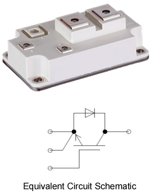
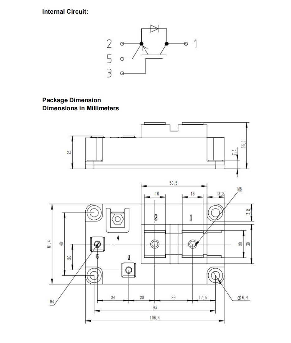
YZPST-FZ600R17KE4
P/N:YZPST-FZ600R17KE4
1700V/600ASingle Switches
Features:
1700V600A,VCE(sat)(typ.)=3.0V
Ultrafast switching speed
Excellent short circuit ruggedness
62mm single module
General Applications:
Daxin’s IGBTs offer ultrafast switching speed for application such as welding, inductive
heating, UPS and other high frequency applications
Absolute Maximum Ratings of IGBT
|
VCES |
Collector to Emitter Voltage |
1700 |
V |
|
|
VGES |
Continuous Gate to Emitter Voltage |
±30 |
V |
|
|
IC |
Continuous Collector Current |
TC = 25°C |
1200 |
A |
|
TC = 100°C |
600 |
|||
|
ICM |
Pulse Collector Current |
TJ = 150°C |
1200 |
A |
|
PD |
Maximum Power Dissipation (IGBT) |
TC = 25°C, TJ = 150°C |
2660 |
W |
|
tsc |
Short Circuit Withstand Time |
> 10 |
µs |
|
|
TJ |
Maximum IGBT Junction Temperature |
150 |
°C |
|
|
TJOP |
Maximum Operating Junction Temperature Range |
-40 to +150 |
°C |
|
|
Tstg |
Storage Temperature Range |
-40 to +125 |
°C |
|
Absolute Maximum Ratings of Freewheeling Diode
|
VRRM |
Repetitive Peak Reverse Voltage Preliminary Data |
1700 |
V |
|
|
IF |
Diode Continuous Forward Current |
TC = 25°C |
1200 |
A |
|
TC = 100°C |
600 |
|||
|
IFM |
Diode Maximum Forward Current |
1200 |
A |
|
Electrical Characteristics of IGBT at TJ = 25°C (Unless Otherwise Specified)
|
Parameter |
Test Conditions |
Min |
Typ |
Max |
Unit |
||
|
BVCES |
Collector to Emitter Breakdown Voltage |
VGE = 0V, IC = 1mA |
1700 |
|
|
V |
|
|
ICES |
Collector to Emitter Leakage Current |
VGE = 0V,VCE = VCES |
|
|
5 |
mA |
|
|
IGES |
Gate to Emitter Leakage Current |
VGE = ±30V, VCE = 0V |
|
|
400 |
nA |
|
|
VGE(th) |
Gate Threshold Voltage |
IC = 1mA, VCE = VGE |
4.5 |
|
5.7 |
V |
|
|
VCE(sat) |
Collector to Emitter Saturation Voltage (Module Level) |
IC = 600A, VGE = 15V |
TJ = 25°C |
|
3.00 |
3.20 |
V |
|
TJ = 125°C |
|
3.60 |
|
||||
Related Products


