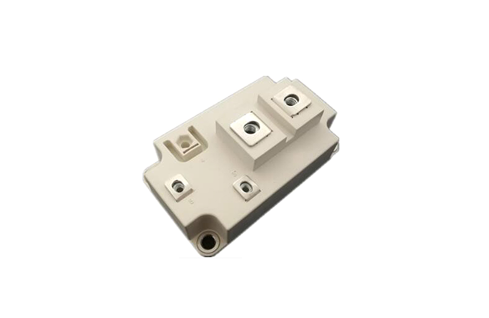
ABSOLUTE MAXIMUM RATINGS TC=25°C unless otherwise specified
|
Symbol
|
Parameter
|
Test Conditions
|
Values
|
Unit
|
|
IGBT
|
|
|
VCES
|
Collector - Emitter Voltage
|
TVj=25°C
|
1250
|
V
|
|
VGES
|
Gate - Emitter Voltage
|
|
±30
|
V
|
|
IC
|
DC Collector Current
|
TC=25°C
|
450
|
A
|
|
TC=80°C
|
300
|
A
|
|
ICM
|
Repetitive Peak Collector Current
|
tp=1ms
|
600
|
A
|
|
Ptot
|
Power Dissipation Per IGBT
|
|
3000
|
W
|
|
Diode
|
|
VRRM
|
Repetitive Reverse Voltage
|
TVj=25°C
|
1250
|
V
|
|
IF(AV)
|
Average Forward Current
|
TC=25°C
|
450
|
A
|
|
TC=80°C
|
300
|
A
|
|
IFRM
|
Repetitive Peak Forward Current
|
tp=1ms
|
600
|
A
|
|
I2t
|
|
TVj =125°C, t=10ms, VR=0V
|
19000
|
A2s
|
ELECTRICAL AND THERMAL CHARACTERISTICS TC=25°C unless otherwise specified
|
Symbol
|
Parameter
|
|
Test Conditions
|
Min.
|
Typ.
|
Max.
|
Unit
|
|
IGBT
|
|
|
|
|
|
|
|
|
|
|
VGE(th)
|
Gate - Emitter Threshold Voltage
|
VCE=VGE, IC=2.0mA
|
|
5.0
|
|
6.8
|
V
|
|
VCE(sat)
|
Collector - Emitter
|
IC=300A, VGE=15V, TVj=25°C
|
|
2.2
|
2.6
|
V
|
|
Saturation Voltage
|
IC=300A, VGE=15V, TVj=125°C
|
|
2.4
|
|
V
|
|
|
|
|
|
ICES
|
Collector Leakage Current
|
VCE=1250V, VGE=0V, TVj=25°C
|
|
|
1
|
mA
|
|
VCE=1250V, VGE=0V, TVj=125°C
|
|
|
5
|
mA
|
|
|
|
|
|
|
Rgint
|
Integrated Gate Resistor
|
Per switch
|
|
10
|
|
Ω
|
|
IGES
|
Gate Leakage Current
|
VCE=0V,VGE±15V, TVj=125°C
|
-500
|
|
500
|
nA
|
|
Cies
|
Input Capacitance
|
VCE=25V, VGE=0V, f =1MHz
|
|
21
|
|
nF
|
|
Cres
|
Reverse Transfer Capacitance
|
|
1.5
|
|
nF
|
|
|
|
|
|
|
|
|
td(on)
|
Turn - on Delay Time
|
VCC=600V,IC=300A,
|
TVj =25°C
|
|
90
|
|
ns
|
|
RG =4.7Ω,
|
TVj =125°C
|
|
110
|
|
ns
|
|
|
|
|
|
|
tr
|
Rise Time
|
VGE=±15V,
|
TVj =25°C
|
|
55
|
|
ns
|
|
Inductive Load
|
TVj =125°C
|
|
60
|
|
ns
|
|
|
|
|
|
|
td(off)
|
Turn - off Delay Time
|
VCC=600V,IC=300A,
|
TVj =25°C
|
|
460
|
|
ns
|
|
RG =4.7Ω,
|
TVj =125°C
|
|
500
|
|
ns
|
|
|
|
|
|
|
tf
|
Fall Time
|
VGE=±15V,
|
TVj =25°C
|
|
55
|
|
ns
|
|
Inductive Load
|
TVj =125°C
|
|
60
|
|
ns
|
|
|
|
|
|
|
Eon
|
Turn - on Energy
|
VCC=600V,IC=300A,
|
TVj =25°C
|
|
28
|
|
mJ
|
|
RG =4.7Ω,
|
TVj =125°C
|
|
12
|
|
mJ
|
|
|
|
|
|
|
Eoff
|
Turn - off Energy
|
VGE=±15V,
|
TVj =25°C
|
|
25
|
|
mJ
|
|
Inductive Load
|
TVj =125°C
|
|
13
|
|
mJ
|
|
|
|
|
|
|
ISC
|
Short Circuit Current
|
tpsc≤10µS , VGE=15V
TVj=125°C,VCC=720V
|
|
1300
|
|
A
|
|
|
|
|
|
|
|
|
|
|
|
RthJC
|
Junction-to-Case Thermal Resistance (Per IGBT)
|
|
|
0.13
|
K /W
|
|
Diode
|
|
|
|
|
|
|
|
|
|
|
VF
|
Forward Voltage
|
IF=300A , VGE=0V, TVj =25°C
|
|
2
|
2.4
|
V
|
|
IF=300A , VGE=0V, TVj =125°C
|
|
2.2
|
|
V
|
|
|
|
|
|
|
Qrr
|
Reversed Chargr
|
IF=300A , VR=600V
|
|
|
50
|
|
uC
|
|
IRRM
|
Max. Reverse Recovery Current
|
diF/dt=-2400A/μs
|
|
|
170
|
|
A
|
|
Erec
|
Reverse Recovery Energy
|
TVj =125°C
|
|
|
20
|
|
mJ
|
|
RthJCD
|
Junction-to-Case Thermal Resistance
|
(Per Diode)
|
|
|
|
0.12
|
K /W
|
MODULE CHARACTERISTICS TC=25°C unless otherwise specified
|
Symbol
|
Parameter
|
Test Conditions
|
Min.
|
Typ.
|
Max.
|
Unit
|
|
TVj max
|
Max. Junction Temperature
|
|
|
|
175
|
°C
|
|
TVj op
|
Operating Temperature
|
|
-40
|
|
150
|
°C
|
|
Tstg
|
Storage Temperature
|
|
-40
|
|
125
|
°C
|
|
Visol
|
Insulation Test Voltage
|
AC, t=1min
|
3000
|
V
|
|
Torque
|
To-Sink
|
Recommended(M6)
|
1.1
|
|
2
|
N·m
|
|
Torque
|
To Signal Terminal
To Power Terminal
|
Recommended(M6)
Recommended(M)
|
3
1.1
|
|
5
2
|
N·m
|
|
Weight
|
|
|
|
328
|
|
g
|
For more information about IGBT Module please download the PDF file above named " YANGZHOU POSITIONING TECH CO Power thyristor and diode parts "


.jpg?x-oss-process=image/resize,w_100/quality,q_100)
.jpg?x-oss-process=image/resize,w_100/quality,q_100)
.jpg?x-oss-process=image/resize,w_100/quality,q_100)
.jpg?x-oss-process=image/resize,w_100/quality,q_100)

